The Dhyana 401D and the FL20-BW use a form of triggering via an optocoupler isolated circuit – a widely-used industrial standard used to isolate the camera’s precise electronics from any external electrical surges or interference. The requirements of optocoupler isolated triggering circuits are slightly different to those of the TTL standard used in other cameras.
The optocoupler itself is a solid state component consisting of a light emitting diode (LED), and a photosensitive transistor, which acts like a switch. When the camera wants to output a trigger signal, a tiny amount of light is sent from the LED to the light-sensitive transistor, which then allows current to flow through it. But the two circuits remain completely isolated from each other, meaning the camera is protected from any electrical interference from the external device. Likewise, input triggers activate optocouplers to pass their signals into the camera.

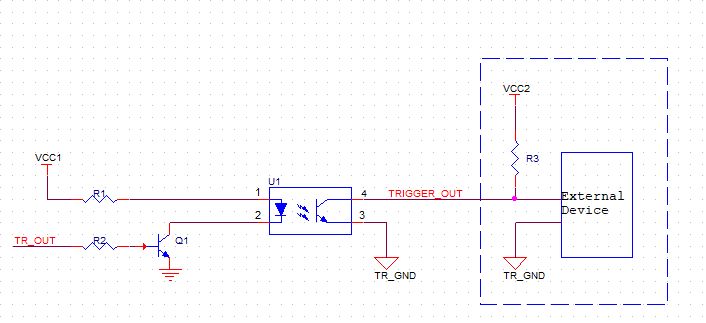
Example triggering setup for optocoupler-isolated triggering circuits. The dashed blue box shows the equipment external to the camera. The line marked ‘TRIGGER OUT’ is the Trigger Out pin of the camera. This entire circuit is repeated in the case of multiple Trigger Out pins. The voltage source VCC2 and the resistor R3 must be added by the user.
Unlike in TTL triggers where the camera’s trigger out connection can directly control the voltage sent along the trigger cable, for example sending a 5V high signal to an external device, optocoupler-isolated circuits act more like a switch, just controlling whether a complete circuit is made or not. The voltage in that circuit must be set (also known as ‘pulled up’) externally through a resistor. Lastly to create the complete circuit the trigger circuit must be connected to ground – the camera has a ‘Trigger Ground’ pin shown in the Pin-Out Diagrams section below that must be connected to the electrical ground.
As shown in the diagram above, a voltage source VCC2 and resistor R3 must be added. The recommended voltage for is 5V – 24V, depending on the voltage that the trigger in connection of your external device expects, though for most devices this may be 5V. The resistor R3 determines the current that flows in the circuit, and the recommended resistance is 1KΩ.
Setting up Trigger Out
When the camera wants to output a trigger signal, the optocoupler circuit is closed and current can flow, and the External Device will register the change in voltage.
Note that to use multiple trigger out pins, you need separate circuits with their own voltage source and resistor.
In summary, you need:
1. The Trigger Out pin of the camera that you are using to be connected to the Trigger In port of the external device.
2. Also connected in parallel to the Trigger Out pin line must be a resistor R3, then in series with that a voltage source VCC2, as shown in the diagram.
3. The value of VCC2 should be set to the required trigger in voltage of your device, typically 5V, though a 5V-24V range is supported by the camera.
4. The value of R3 is recommended to be 1KΩ
5. The Trigger Ground pin of the camera must be connected to ground.
6. This circuit should be repeated for each trigger out pin used.
7. Then your circuit is good to go!
Setting Up Trigger In
The setup for Trigger In is identical to that for Trigger Out, connecting the Trigger In connection of the camera to your external device’s output and a voltage source, and the ground pin to ground. Ensure that the input voltage from the external pull-up is within the range 5V-24V.
Trigger Cable & Pin-out Diagrams
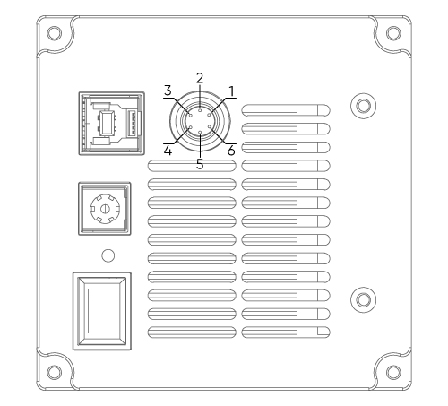
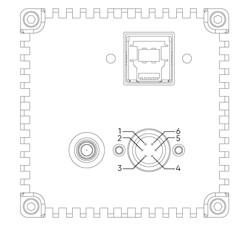
Below find the pin-out diagrams for the FL20BW (left) and Dhyana 401D (right). These cameras use a Hirose breakout cable to allow easy access to each pin. Below this is the table of functions for each pin, which is the same for both cameras.


Trigger pin diagrams for the FL20BW (left) and the Dhyana 401D (right). Note the location of the USB and power connectors to ensure the camera is in the correct orientation for discerning pin numbers.
| Pin on Hirose Connector | Pin Name | Explanation |
|
1 |
TRI_IN |
Trigger In signal to control camera acquisition timing |
|
2 |
TRI_GND TRI |
Ground pin. This must be connected to the electrical ground for triggers to operate. |
|
3 |
NC |
Not Connected – no function |
|
4 |
TRI_OUT0 |
Trigger Out - Exposure Start signals |
|
5 |
TRI_OUT1 |
Trigger Out – Readout End signals |
|
6 |
NC |
Not Connected – no function |
Ensure that your triggering circuit is set up as in the ‘Introduction to setting up triggering…’ section above, including the voltage source, resistor, and the ground cable connected to an electrical ground, and you should be ready to set up the desired trigger modes in software.
Trigger In Modes & Settings
When the camera is operating in a ‘Hardware Trigger’ mode, the acquisition of frames will be triggered by signals on the Trigger In cable.
There are a few settings to optimize and choose for your application, available in your software package. The screenshot below shows how these settings appear in Tucsen’s Mosaic software.

Hardware Trigger Setting
For the FL20BW and Dhyana 401D, only ‘Off’ and ‘Standard’ modes are operational.
Off: In this mode, the camera is ignoring external triggers, and running at full speed on internal timing.
Standard: In this mode, each frame of the camera’s acquisition will require an external trigger signal. The ‘Exposure’ and ‘Edge’ settings determine the nature and behavior of this signal & acquisition.
Exposure Setting
The duration of the exposure time of the camera can be controlled either by software, or by external hardware via the duration of the trigger signal. There are two settings for Exposure:
Timed: The camera exposure is set by the software.

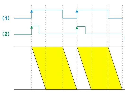
Diagram showing Timed mode triggering behavior, with Rising Edge trigger mode. The beginning of each exposure is synchronized with the rising edge of an external trigger pulse, with the exposure time set by software. Yellow shapes represent camera exposure. 0H, 1H, 2H… represent each horizontal camera row, with a delay from one row to the next due to the rolling shutter of the CMOS camera.
Width: The duration of the high signal (in the case of rising edge mode), or low signal (in the case of falling edge mode) is used to determine the duration of the camera’s exposure time. This mode is also sometimes known as ‘Level’ or ‘Bulb’ Trigger.

Diagram showing Width mode triggering behavior, with Rising Edge trigger mode. The beginning of each exposure is synchronized with the rising edge of an external trigger pulse, with the exposure time set by the duration of the high signal.
Edge Setting
There are two options for this setting, depending on your hardware setup:
Rising: The camera acquisition is triggered by the rising edge of a low to high signal.
Falling: The camera acquisition is triggered by the falling edge of a high to low signal.
Delay Setting
A delay can be added from the moment of the trigger being received until the camera begins its exposure. This can be set between 0 and 10s, and the default value is 0s.
A note on trigger timing: Ensure triggers are not missed
In each mode, the length of time between triggers (given by the duration of the high signal plus the low signal) must be long enough that the camera is once again ready to acquire an image. Otherwise, triggers sent before the camera is ready to acquire again will be ignored.
The length of time required for the camera to be ready to receive a signal is slightly different between the FL-20BW and the Dhyana 401D.
FL- 20BW: The minimum delay between triggers is given by the exposure time plus the frame readout time. I.e., at the end of an exposure, the frame must be read out before a new trigger can be received.
Dhyana 401D: The minimum delay between triggers is given by either the exposure time or the frame readout time, whichever is greater. I.e., the acquisition of the next frame and readout of the previous frame can overlap in time, meaning a trigger can be received before the end of the readout of the previous frame.

Timing diagram showing the minimum gap between triggers for the FL20-BW in (1) Width exposure mode, and (2) Timed exposure mode, with a Rising Edge trigger. In (1), the duration of the low signal must be equal to or greater than the readout time for the camera. In (2), the duration of the high signal plus the low signal (i.e. the repeat time / period of the signal) must be greater than the exposure time + the readout time.
Trigger Out Modes & Settings
Once your trigger circuit is set up as indicated in ‘Setting Up Trigger Out’ above, you’re ready to configure the camera to send triggers appropriately for your application.
Trigger Out Ports
The camera has two Trigger Out ports, Port1 and Port2 each with their own Trigger Out pin (TRIG.OUT0 and TRIG.OUT1 respectively). Each can operate independently and be connected to separate external devices.
Trigger Out Kind

Diagram demonstrating the effect of different ‘Trigger Out: Kind’ Settings, in this case for Edge: Rising. The ‘Exposure Start’ trigger goes high when the first row begins its exposure. The Readout End trigger goes high when the last row ends its readout.
There are two options for what phase of camera operation the trigger output should indicate:
Exposure Start sends a trigger (from low to high in the case of ‘Rising Edge’ triggers), at the moment that the first row of a frame begins exposure. The width of the trigger signal is determined by the ‘Width’ setting.
Readout End indicates when the last row of the camera ends its readout. The width of the trigger signal is determined by the ‘Width’ setting.
Trigger Edge
This determines the polarity of the trigger:
Rising: The rising edge (from low to high voltage) is used to indicate events
Falling: The falling edge (from high to low voltage) is used to indicate events
Delay
A customizable delay can be added into the trigger timing, delaying all Trigger Out event signals by the time specified, from 0 to 10s. The delay is set to 0s by default.
Trigger Width
This determines the width of the trigger signal used to indicate events. The default width is 5ms, and the width can be customized between 1μs and 10s.


 2023/01/27


